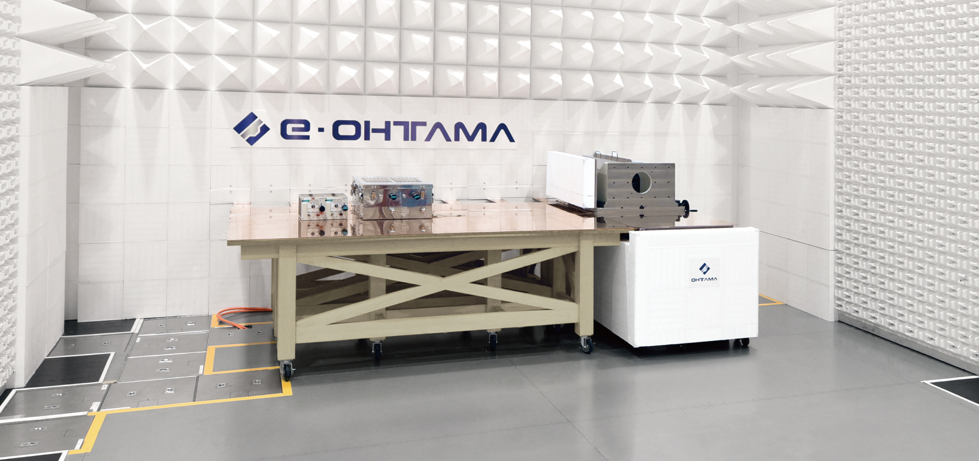


e-MotorChamber Demonstration Anechoic Chamber Equipment
This page introduces the system equipment such as the long shaft and dynamometer.
We will also explain optional extras available when purchasing a new or modified system, including delivery dates and a rough schedule for deployment.
*The demonstration anechoic chamber is located in the Fujimatsu Laboratory at the Tokai EMC Center of e-OHTAMA, LTD.
-
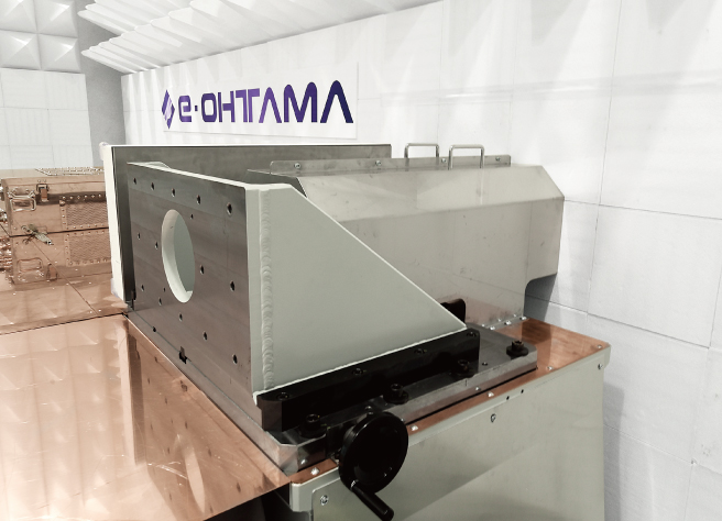
Shaft
The system uses a shaft with a length that can secure a distance of 1,000 mm or more from the microwave absorber to the test sample. Noise transmitted from the shaft that penetrates the wall of the anechoic chamber is also eliminated.
*The shaft is covered with metal for safety reasons.Motor mounting part
We can also supply a test motor mounting jig (please contact e-OHTAMA).
-
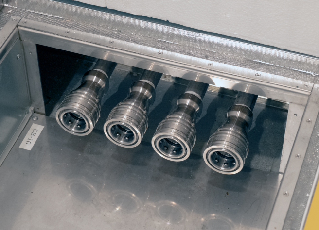
Cooling chiller (for test sample)
The system is equipped with a chiller that offers both water cooling and oil cooling.
-
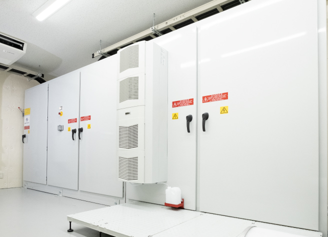
Inverter and battery simulator
Size:5,000 x 700 x 2,500 mm (W x D x H)
-
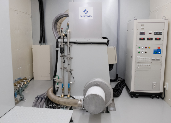
Dynamometer
The dynamometer achieves high-speed rotation of 20,000 rpm or more. It is also possible to comply with the greater specifications of future standards.
*The dynamometer is covered with metal for safety reasons. -
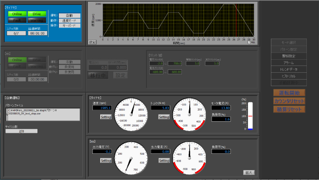
System control software
Dynamometer and Battery simulator can be arbitrarily controlled manually or programmatically.
-
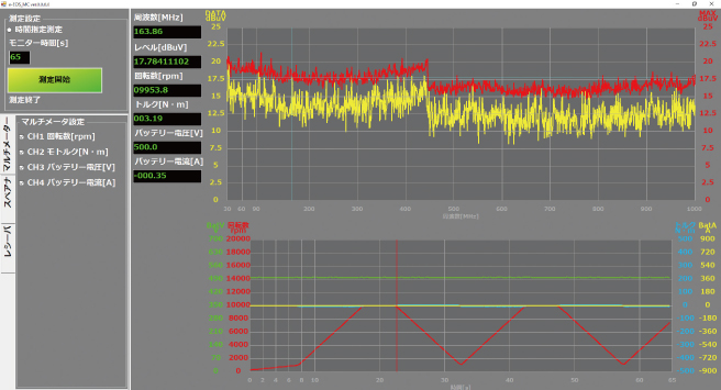
System-linked EMI mesurement software
Originally developed software enables EMI measurement linked to the operational conditions of the EUT motor including rotation, torque, voltage and current. This reduces the time required to identify the operating conditions when the worst interference noise level observed.
-
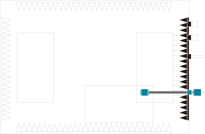
Anechoic chamber and test layout
At the e-OHTAMA Fujimatsu Laboratory, which has a demonstration anechoic chamber, absorbers are installed on five sides. In addition, the copper table-top (2,700 × 1,500 mm), on which the sample system is mounted, can be moved within the anechoic chamber if necessary.
■ Position of copper table-top A, B: For an EV motor test
■ Position of copper table-top C: For tests other than those for EV motorsRecommended specifications for remodeling/new construction Anechoic chamber: 7,000 × 7,000 × 4,300 mm (W × D × H) or more
Optional Extras
The dynamometer room, amplifier room, and measurement room
are optional equipment for both new and remodeled systems.
-
Dynamometer room
(soundproof specification)Recommended size:
7,000 × 4,000 × 2,600 mm (W × H × D) or larger -
Amplifier room
Recommended size:
Customer’s specifications -
Measurement room
(shield specifications)Recommended size:
Customer’s specifications
Specifications
| Demonstration Anechoic Chamber (Fujimatsu Laboratory) |
Customization | ||
|---|---|---|---|
| Dynamometer |
Rotation speed(rpm) |
20,000 |
Negotiable up to 25,000 |
| Battery simulator |
Voltage(V) |
DC 700 |
Up to DC 1,250 |
- *We can also provide services such as selecting test equipment, training and dispatching test operators, and calibrating test equipment for you.
Overview Flow Diagram

-
*The construction work at the customer's site is expected to take a total of 5 months, with it taking 3 months
to construct the anechoic chamber and 2 months for delivery and adjustment of the motor and inverter. -
*From entering into a contract to delivery of the system usually takes about one year, which includes the time it takes
to produce the motor and inverter, however, this timeframe does depend on the specifications. - *This flow chart shows the approximate process from beginning to end. The actual schedule will change depending on the specific conditions of the project.